
Application / EPTEK tooling

Carbon-Fibre Lay-Up Tooling

Carbon-fibre lay-up tooling follows two typical routes: a high-end prepreg and autoclave route with low-temperature cure, high-temperature post-cure and high-temperature use; or a lower-cost vacuum-infusion route selected around the required service temperature and production duty.

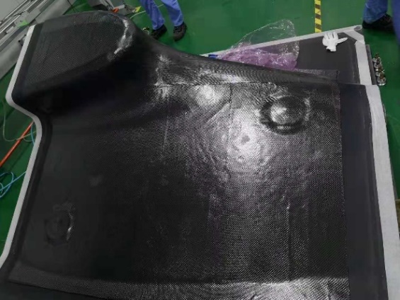
Carbon-fibre lay-up tooling surface
EPTEK / TOOLING EXPERTISECarbon-Fibre Lay-Up Tooling

Two typical process routes

Choose the cure route before the material grade.

The mould structure, carbon reinforcement, resin system, vacuum or pressure process and post-cure must be designed as one tooling system. The service temperature of the finished mould is only one part of that decision.

01 / HIGH-END ROUTE

Prepreg lay-up and autoclave forming

Tooling prepreg is laid up under controlled storage, conditioning, debulk and bagging conditions, then cured in the autoclave. The typical route is low-temperature initial cure, high-temperature post-cure and high-temperature use of the finished carbon-fibre tool.

LTP220 and LTP240 are the typical EPTEK tooling-prepreg choices for this route. LTP240 is the high-temperature-curing version; the selected lay-up, cure and post-cure schedule must follow the current TDS and project process specification.

02 / LOWER-COST ROUTE

Vacuum-infusion mould manufacture

A carbon-fibre mould can also be made by vacuum infusion when a lower-cost liquid-resin route is preferred. Dry reinforcement, vacuum integrity, fibre wet-out, laminate thickness, exotherm and post-cure determine the dimensional result and repeatability.

For a carbon-fibre lay-up tool used around 180°C, the project route may use LTP220LV as specified by EPTEK. For a tool used around 120°C, EPMOLD170LV is the typical lower-temperature liquid-resin choice. Confirm the current controlled TDS and cure schedule for the exact project.

Surface strategy

Do not hide the mould surface under a gelcoat by default.

For carbon-fibre lay-up moulds, EPTEK does not recommend adding a gelcoat as a default surface layer. A direct, properly finished tool surface makes pinholes, print-through, local defects and other process problems visible during manufacture. They can then be repaired and inspected before the mould enters production. Covering the surface can conceal those problems and make reliable correction harder, reducing the useful life of the tool.

INSPECT

Keep defects visible

Inspect the carbon tool surface after cure, post-cure, machining and finishing. Record the areas that need repair instead of sealing them behind an opaque layer.

REPAIR

Repair before release

Use the appropriate tooling repair method, re-finish the local area and verify the surface against the master or inspection datum before applying release materials.

DURABILITY

Build service life into the process

A visible and repairable tool surface supports earlier correction, more consistent release and longer mould life when the laminate and cure route are controlled.

Engineering checkpoints

Record the whole cure history.

CheckpointWhy it matters
Storage and conditioningPrepreg out-time, temperature and handling affect consolidation and cure consistency.
Vacuum or autoclave pressureBag integrity, debulk and pressure determine fibre wet-out, void control and tool thickness.
Cure and post-cureFollow the grade-specific schedule and record actual temperature history before machining or release.
Surface inspection and repairCheck the direct tool surface, correct defects and verify finish before production.
Thermal cycling and part countSet the expected service temperature, cycling and number of parts before choosing the route.