Application / Aerospace tooling

Master Models for Carbon-Fibre Tooling

The master model establishes the geometry and finish that a carbon-fibre mould will reproduce. Its construction must remain stable through the mould lay-up, initial cure and release process. EPTEK supports four distinct manufacturing methods.

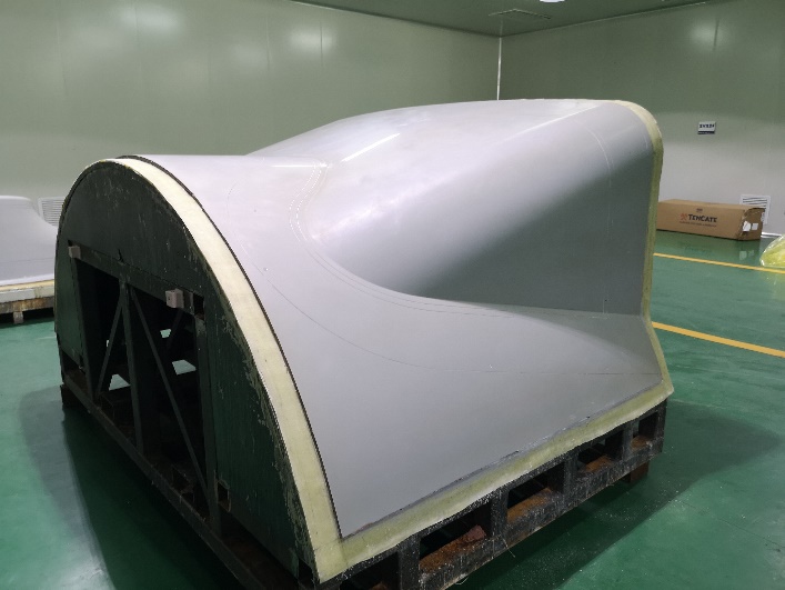
Finished master model surface supported on a steel-frame construction, from EPTEK aerospace presentation
EPTEK / APPLICATIONThe finished master defines the mould surface

Engineering requirements

Four ways to build the master

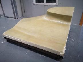
Glass-fibre skin on a foam-supported master model

01 / FOAM-BASED BUILD

PU foam + glass-fibre skin + tooling paste + gelcoat

Shape the foam substrate, laminate the glass-fibre skin, then apply the epoxy tooling paste. CNC machine the cured working layer and finish with the specified gelcoat. The skin distributes local loads; the paste provides the machining allowance.
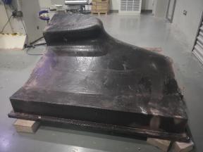
Cured filled-resin master-model blank after demoulding

02 / CAST BLANK

Cast PU or epoxy resin with fillers

Prepare the casting cavity and pour the selected filled tooling system under its prescribed thickness and cure conditions. Demould the cured blank, machine it to CAD geometry and finish the surface. Control heat build-up, voids and shrinkage during casting.

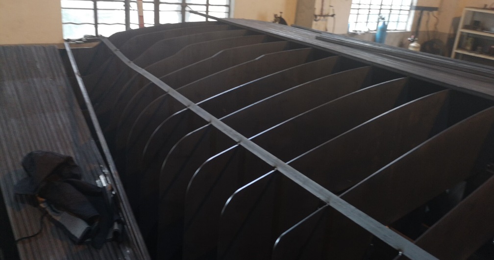
Steel support frame for a glass-fibre and tooling-paste master model

03 / FRAME-BASED BUILD

Steel frame + glass-fibre skin + tooling paste + gelcoat

Build the support frame, form and seal the glass-fibre skin, then apply and machine the tooling paste. Finish the working surface with a compatible gelcoat. Frame restraint, skin support and thermal movement must be considered together.

Master tooling produced from bonded and machined boards

04 / BONDED BLOCK

Bonded board stack-up + CNC machining

Cut and bond the selected boards into a blank with a compatible adhesive. Allow the bondlines to cure before referencing and CNC machining. Check seams, surface finish and the stability of both board and adhesive through the subsequent mould-making cycle.

Engineering requirements

Select each material for its role

ConstructionEPTEK materialsKey decision
Foam-supported masterPUFOAM + EPLAM laminating systems + EPMOLD tooling pastes + gelcoatFoam support, skin integrity, paste thickness and compatible cure
Filled castingPUCAST or EPCAST systemsCasting volume, filler package, exotherm, cure and machining allowance
Steel-frame masterEPLAM + EPMOLD + gelcoatFrame design, local support and surface-layer continuity
Board masterPUBOARD model boards or EPBOARD epoxy tooling boards, with matched adhesiveTemperature during mould manufacture, size, seams and required finish

Engineering requirements

Qualify the complete master

Start with the dimensional tolerance, model size, surface finish and the actual initial cure cycle of the carbon-fibre mould. Confirm the board or resin, joints, coating and support structure together. The eventual service temperature of the finished composite mould does not by itself define the master material.